
Instrument Expert
Original factory packaging

Service Hotline:
(+86)010-52867771
Instrument Expert
Original factory packaging
Service Hotline:
(+86)010-52867771
Updated:2025-03-13
Views:5130
 WeChat
 QQ
QQ
 Online Service
 Datasheet
The TS250 waveform amplifier is a unique instrument ideal for amplifying function generator. It amplifies current or voltage or power for driving heavy loads. The TS250 offers eight voltage ranges to choose from ±10V to +65V. The TS250 output current up to 5A for the low-voltage model. Higher current is possible by connecting two or more TS250 waveform amplifiers in parallel as shown in the Application Section.
The TS250 waveform amplifier is ideal for many test and measurement applications such as LDO and amplifier PSRR test, battery simulator, op-amp CMRR measurement, high current driver for electromagnetic and Helmholtz coils, general function generator amplifier, transient response test, four-quadrant power supply, lab power amplifier and more.
High-Current Amplifier
TS250 is ideal as a function generator amplifier for amplifying current. It can drive high current or high power or high voltage loads. It can output up to 6A peak for the low-voltage model and reduced current for the higher voltage models. As a current amplifier, it accepts AC or DC voltage input from a function generator to drive a heavy load that requires high current. The TS250 waveform amplifier features a selectable gain of 0dB or 20dB.
Battery Simulator
TS250 can source or sink current. It can be used as a battery simulator and emulator. It has a variable DC output that can easily simulate battery voltage changes. Thus it is great for battery charger testing such as those in battery operated portable electronic systems.
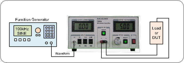
Waveform Amplifier Connection
Waveform Amplifier Basic Theory of Operation
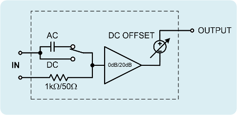
Figure 1. TS250 waveform amplifier functional equivalent diagram.
Figure 1 shows the TS250 waveform amplifier functional equivalent diagram. It consisted of an AC-coupled or DC-coupled input, a selectable input impedance (high-impedance or 50Ω), a selectable gain stage (0dB or 20dB), high current amplifier, and a DC output offset. The adjustable DC offset sets the output DC voltage. This DC offset feature is ideal for LDO or amplifier PSRR measurement, because they require a DC voltage.
Input AC/DC Couple
The TS250 waveform amplifier input signal is applied to the BNC connector on the front panel. The input is first conditioned by the selectable coupling. The TS250 input is either AC-coupled or DC-coupled. This allows added flexibility for the TS250 to work with a variety of instruments such network analyzers and function generators. Use the AC-coupled setting to blocks out any input DC voltage. Use the DC-couple setting to allow the source DC voltage to be amplified. In the case where you want the waveform amplifier outputs the same voltage as the function generator for example, use DC-couple, 50Ω, 0dB gain, and adjust the DC offset to 0V.
Input Impedance
The TS250 features a selectable input termination impedance. The input impedance is either high-impedance (1kΩ) or 50Ω. Most signal generators expect 50Ω termination. The 50Ω setting also achieves the lowest noise. If AC-couple and 50Ω setting are used, the input lower cutoff frequency is about 50Hz.
Some signal source cannot drive 50Ω termination. In that case, use high impedance termination. If AC-couple and high impedance are used, the lower cutoff frequency is about 50Hz.
Amplifier Gain
The TS250 features selectable gains: 0dB or 20dB. Most function and arbitrary waveform generators output ±5V into 50Ω. For higher output voltage, gain is necessary. The 20dB gain setting will amplify the input by a factor of 10. The 0dB setting is unity gain (gain of 1). The TS250 waveform amplifier offers flexible gains to accommodate many waveform generators.
High Current Output
The TS250 output is on a pair of banana binding posts. The output pair is labeled as “+” and “-”. The “+” terminal is the positive output while the “-” terminal is the negative output. The OUTPUT negative terminal shares a common connection with the Current-Monitor Output BNC (negative) connector in the back panel. However, the OUTPUT negative terminal does not directly connected to Input BNC ground. In normal usages, OUTPUT negative terminal is connected to the common “Ground”.
Upon power up, the OUTPUT is disabled. The ON/OFF button light is off. The OUTPUT is enabled by press-and-hold the ON/OFF button for about 200ms and released it. The LED light is on when the output is enabled. Press-and-hold the ON/OFF button for about 200ms and released it will turn off the output.
Fault Conditions
The TS250 is protected by a number of fault protections. These fault protections are: output over-current, input over-voltage, over-heating (thermal), and under voltage. If a fault is occurred, the output is disabled and the ON/OFF LED light is flashing. After the fault condition is removed, press-and-hold the ON/OFF button for 200ms will exit the fault condition. Press-and-hold the ON/OFF button for 200ms again will re-enable the output. If the fault condition is still existed (e.g. not yet cool down), the waveform amplifier will re-enter the fault condition and the LED light keep flashing.
Input Over-Voltage
The TS250 features an input over-voltage protection. If the input peak voltage is over or under the threshold, both the input and output will be disconnected. The waveform amplifier will enter a fault condition and the ON/OFF LED will be flashing. Once the over-voltage fault is removed, press-and-hold the ON/OFF button for 200ms will exit the fault condition. Press-and-hold the ON/OFF button for 200ms again will enable the output. The typical positive and negative over-voltage thresholds are shown in Table 1. If the input is set to AC-couple and the input is DC voltage, over-voltage will not be detected. The absolute maximum input voltage is ±20V for any input setting.
| Model | Z Setting | Positive | Negative |
| TS250-0/1/2/3 | Hi-Z | +10.5V | -10.5V |
| TS250-4/5/6/7 | Hi-Z | +10.5V | -9.3V |
| TS250-0/1/2/3 | 50 ohm | +6.5V | -6.5V |
| TS250-4/5/6/7 | 50 ohm | +6.5V | -5.7V |
Table 1. Waveform Amplifier input over-voltage thresholds.
Output Over-Current
The TS250 features an output over-current protection. If the output current is over the threshold, the waveform amplifier output will be disconnected. The TS250 will enter a fault condition and the ON/OFF LED will be flashing. Once the over-current fault is removed, press-and-hold the ON/OFF button for 200ms will exit the fault condition. Press-and-hold the ON/OFF button for 200ms again will enable the output. The typical over-current thresholds are shown in Table 2.
| Model | Over-Current Threshold |
| TS250-0 _ | 6.0A RMS |
| TS250-1 _ | 3.3A RMS |
| TS250-2 _ | 2.3A RMS |
| TS250-3 _ | 1.9A RMS |
| TS250-4 _ | 4.1A RMS |
| TS250-5 _ | 2.3A RMS |
| TS250-6 _ | 1.9A RMS |
| TS250-7 _ | 2.3A RMS |
Table 2. Input over-voltage thresholds.
Output DC Voltage Offset
The TS250 features a DC OFFSET output. This feature is useful for waveforms that contained an AC waveform on top of a DC voltage such as PSRR, CMRR, and line transient tests. The OFFSET knob adjusts the DC voltage. In other applications where zero DC voltage is preferred, press and release the OFFSET ON/OFF button to disable the DC offset voltage. When DC offset is disabled, the LED light is off too.
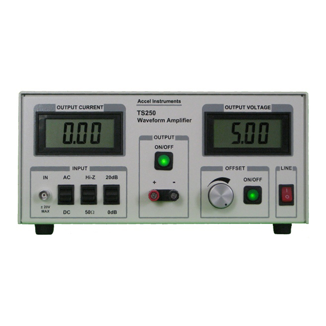
LCD LCD Current and Voltage Displays
The TS250 features two large LCD displays. The one on the left is the output current display. The one on the right is the output voltage display. A positive current indicates the current is sourced out of the TS250 waveform amplifier. A negative current indicates the current is sink into the TS250. Both LCD display read the average value. For example, a sine-wave with no DC offset will read 0V. A 30% duty cycle 0-to-10V square-wave will read 3.0V.
Current Monitor Output
The TS250 waveform amplifier include a current monitor output that can be connected to an oscilloscope to monitor the waveform current. The current monitor gain scale is 100mV per ampere when terminated into 50Ω. For example, a 2A output current will result in 200mV output voltage on the current monitor output. If the oscilloscope is set to high impedance (1MΩ), the output voltage will be 200mV/A. 50Ω termination is recommended especially for high frequency or square waveforms. If the oscilloscope does not have 50Ω termination build-in, you may purchase the TS220 external 50-ohm terminator from us. Use Figure 2 for connecting the Current Monitor to an oscilloscope. If both current and voltage are monitored as in Figure 2, it is recommended to leave the voltage probe ground lead unconnected.
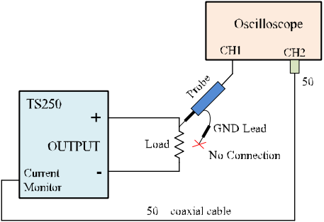
Figure 2. Leave the oscilloscope ground lead unconnected when using current monitor output.
AC Power Input
The TS250 accepts universal AC power input from 100VAC to 240VAC 50/60Hz. It comes with an America-style power cord. Adapter is needed (not included) for any other country outlet.
Higher Output Current
The TS250 output up to 6A peak. If higher current is needed, two or more TS250 waveform amplifier can be connected in parallel as shown in Figure 3. The output current is increase in proportion to the number of TS250 connected in parallel. Series resistors are required to isolate the TS250 from each other. Typical series resistance value is 0.3Ω to 1.0Ω. Higher voltage should use higher resistance. Use power resistor to handle the rated power dissipation.
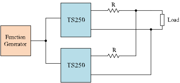
Figure 3. Parallel two TS250 waveform amplifiers doubles the output current.
Customer Service QQ
Customer Hotline:
Technical Supports



 3003988120
 yiqi.com
 bio-equip.com
 b2bwork.baidu.com
 baidu.com